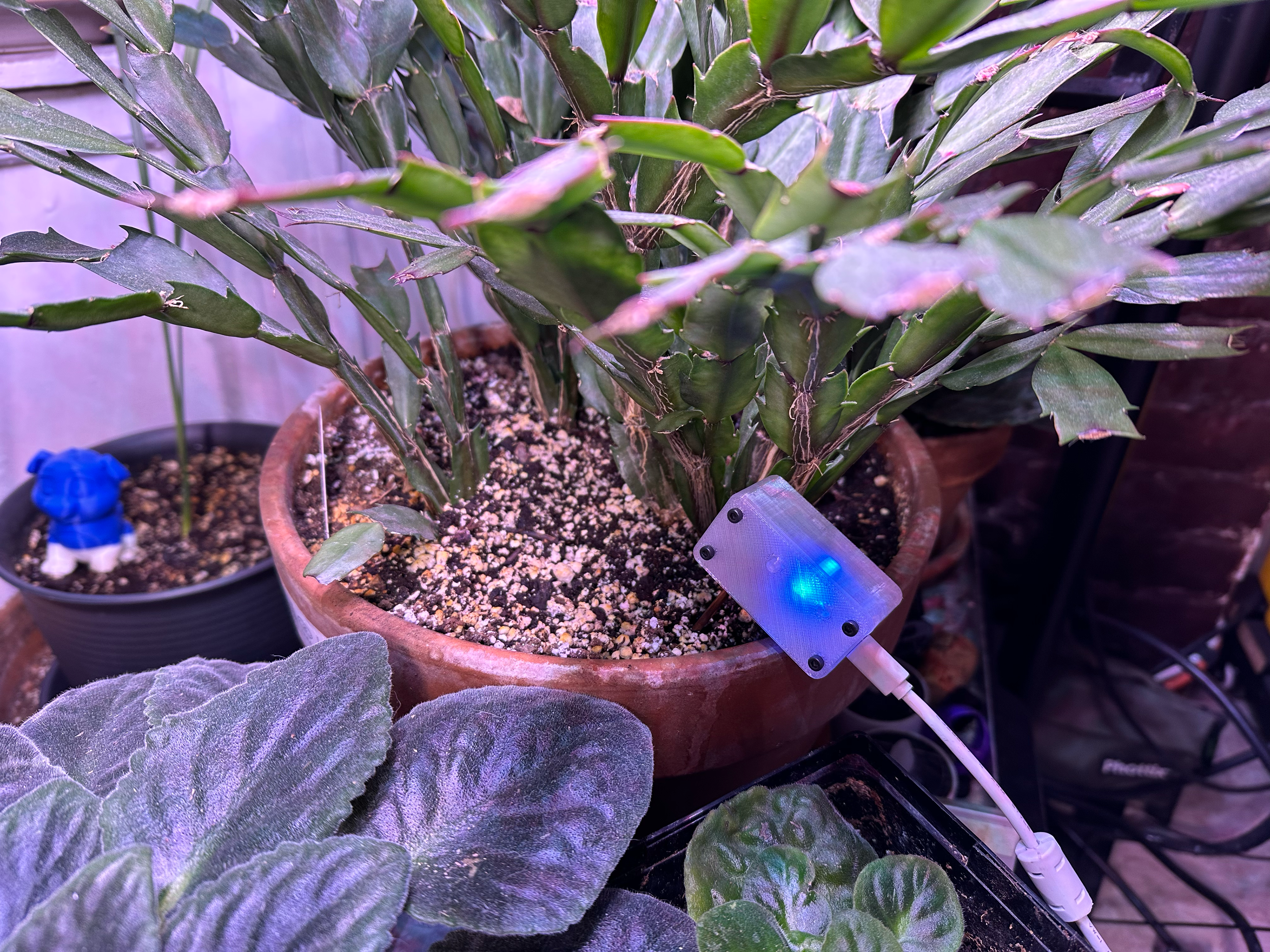
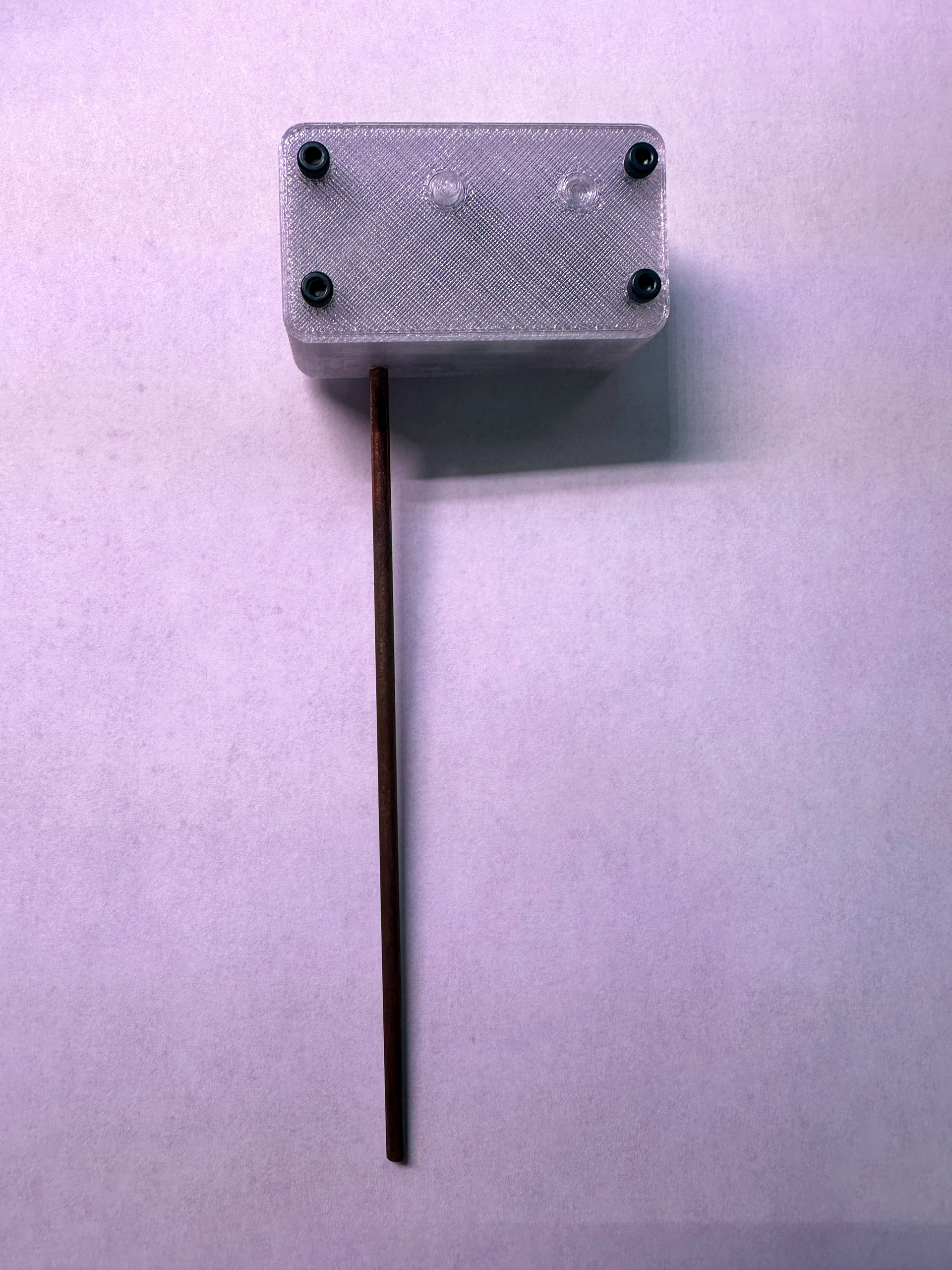
The heart of the Plantini sensor consists of a micro-controller unit (MCU) that is capable of sending Musical Instrument Digital Interface (MIDI) data via the Bluetooth Low Energy (BLE) wireless transmission protocol. The Adafruit Feather nRF52480 Express MCU was chosen because it had a Nordic Semiconductor Bluetooth radio, a fast ARM Cortex M4F microprocessor, and a USB to serial adapter for writing firmware on a single board. BLE was chosen to reduce the number of wires necessary, while eliminating the need for a complex stand-alone WiFi network. A copper rod was attached via a detection circuit to the MCU and inserted into the soil of a potted plant. However, since the circuit required a path to ground, a USB cable was used for power instead of battery power. Perhaps a grounding strap could be used for an installation that has plants connected to the ceiling or floor using a metal stand, but the current solution reduced the need for extremely long USB cables going to a central computer.
The Plantini works as electrons travel from the detection circuit, through the copper probe, the soil and the plant, to a person touching the plant, then to the ground. (See detection circuit diagram below.) When the electrons flow to ground, a voltage drop occurs, which is measured in millivolts (mV). When a voltage threshold has been met, the Max bpatcher outputs a Boolean value of one for a set amount of time, then switches back to zero. This threshold is determined through a calibration algorithm that finds the lowest voltage after five seconds have elapsed, then adds 20 mV of padding to ensure the trigger will occur. In addition, the bpatcher outputs the voltage so that one may utilize the probe for analogue control of anything within Max.

The detection circuit was based on the design used in an educational toy called MaKeyMaKey, which allows one to attach alligator clips to anything that can conduct low voltage electricity. When the object connected to the MaKeyMaKey is touched, a path to ground is established and a computer keyboard command is sent through a USB cable to a computer using the human interface device (HID) protocol. However, the resistor value used in the Plantini needed to be adjusted as the MCU utilized 3.3V logic level inputs instead of the MaKeyMaKey's 5V.
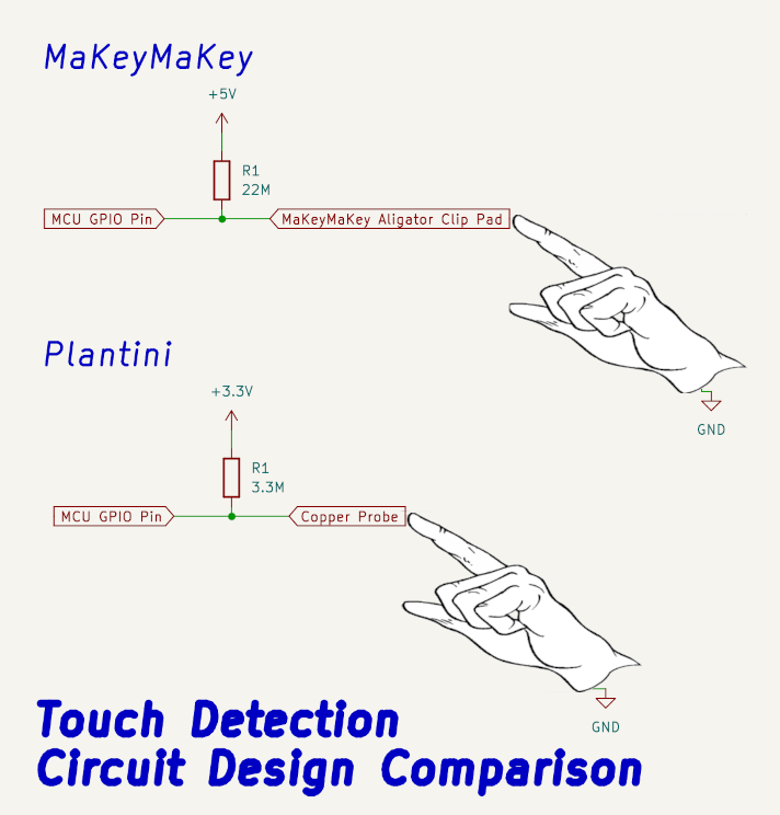
This adjustment was determined through a combination of calculations using Ohm's law and testing with several different resistors in circuit. Eventually, we discovered that a 3.3 MΩ resistor was a perfect fit because it was not overly sensitive to magnetic and electrical interference, but was capable of detecting touches. An accelerometer/gyroscope board utilizing the LSM6DSOX chip was attached to the MCU via the serial peripheral interface (SPI) bus for detecting motion of the plant.
All of the hardware is encased in a plastic enclosure that was printed in polyethylene terephthalate glycol (PETG) plastic using a fused filament fabrication (FFF) style 3D printer. Clear-colored filament was chosen so that all indicator lights would be visible through the case. A light pipe was constructed above a multi-colored light emitting diode (LED) built into the Feather board. This LED indicator appears on the case as a square and shines brightly throughout most of the case. The color may be changed to detect which Plantini is in use, or be changed programmatically during the composition for additional visual effect.
The firmware for the sensor was written in the C++ programming language and utilizes the Arduino platform and libraries. In addition, FortySevenEffects' Arduino MIDI library aided with the formation of MIDI messages to be sent to Cycling '74's Max audio/video programming software. The accelerometer, gyroscope, and probe's voltage data was sent from the MCU using MIDI pitch bend messages, as the values being sent exceeded the typical range of 0-127 that may be sent using most other types of messages. A MIDI pitch bend message consists of a one status byte containing the message type and the MIDI voice channel number followed by two MIDI data bytes.
Since the data bytes contain a bit that indicates the message type, each data byte is limited to seven bits; thus, limiting values to the integer range of -8192 to +8192. The accelerometer values are in meters per second squared (m/s^2) while the gyroscope reports in radians per second. Both of these value types are multiplied by 1000, sent, interpreted, then multiplied by 0.001. Since the probe voltage will never exceed +3300 mV or rarely fall below 0 mV, the voltage is transmitted without manipulation. In Max, the most significant data byte is received, shifted over seven bits, then added to the least significant data byte. The channel is extracted from the status byte and used to determine which of the seven values are being sent: accelerometer x, y, or z; gyroscope x, y, or z; and the probe voltage.